Moving from hand-drafting to computer-aided design and drafting (CADD) was one such moment; doing business in a technology dependent world forced companies to adapt or find themselves struggling to meet shorter deadlines on more complex projects. Now the latest change is the emergence of 3D digital design.
On March 7, 2019, the FDOT announced its transition to OpenRoads Designer (ORD), signaling to Florida’s engineering community that 3D design cleared another hurdle. Consultants must now create design workflows that meet new design development and deliverables standards. Roadway engineers must devise innovative solutions to questions presented by 3D design and ORD. How are design deliverables reviewed at traditional phase milestones? How are Quality Control (QC) processes going to ensure accuracy for a 3D digital deliverable? How will a professional engineer sign and seal this deliverable? We do know the answer to one question — will the time and effort pay off in the long term? Yes!
Project managers and their design teams must develop strategies mitigating pitfalls that often occur using new and unfamiliar software. However, this shouldn’t keep consultants from embracing new and exciting advancements in 3D.
Roadway
To meet consistency, reliability, and accuracy requirements, WGI restructured its design workflow for 3D corridor modeling. WGI emphasized forming a 3D QC and quality assurance (QA) team to match the needs FDOT laid out in the CADD manual. The benefits of a quality template design are accurate quantity reporting throughout every project phase. This applies to both permanent and temporary construction, allowing visualization of milling and resurfacing limits, or checking the asphalt tonnage as design modifications are made in real-time.
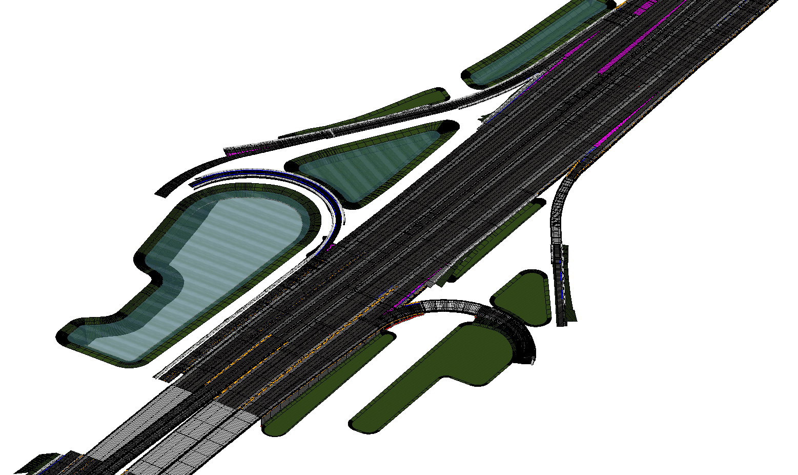
Additionally, the designer can display the project’s proposed surface either with a wire frame or color display indicating slope and elevation changes. This is useful when checking ramp terminals and/or side slopes for discontinuity and also assists with stormwater design and verifying superelevation transitions.
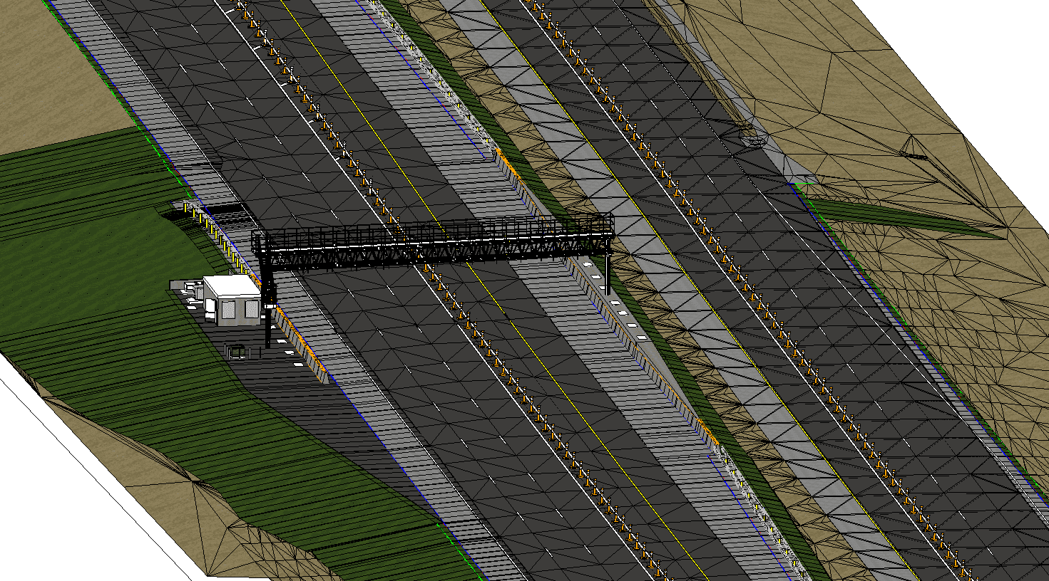
With 3D, the visualization’s benefits are extensive. Design review is moving away from paper and happening more often in the 3D model. The client, contractor, and designer can now conduct a drive-through or fly-through view of an entire proposed project. For example, checking that profiles tie into proposed bridges, or that horizontal geometry won’t cause sight-distance issues, or reviewing the signing and pavement marking at controlled speeds through detailed animations. Critical infrastructure like toll gantries, overhead signs, and bridge construction can be checked for vertical clearance or clear zone violations. Constructability issues may be discovered and avoided earlier in the design process.
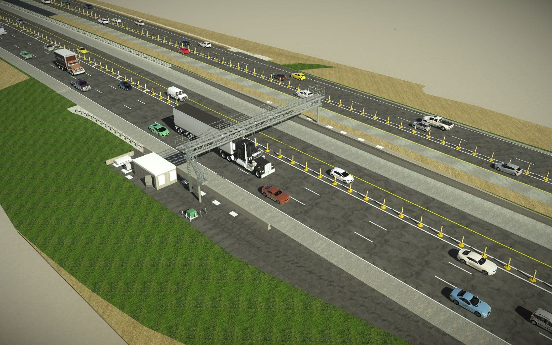
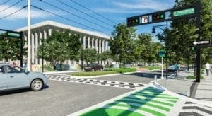
Generating high-quality visuals from the 3D model results in high-resolution renderings and animations for public and stakeholder outreach; for example, eliminating confusion when describing a new corridor by utilizing virtual reality to showcase the design. Another emerging technology used on the job site is augmented reality; all you need is a cell phone or tablet to see proposed conditions overlaid with existing. Virtual and augmented reality will continue to play a bigger role in conveying overall design intent. Just as CADD became the industry standard, these new tools will continue to change the way our transportation corridors are developed, designed, and brought to life.

Bridges
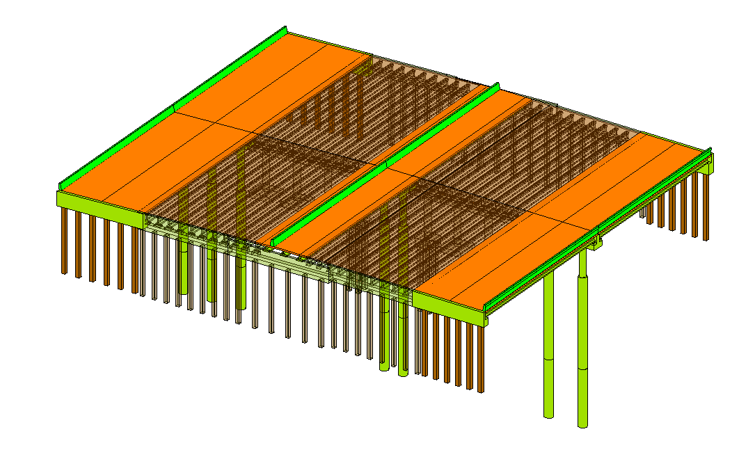
For bridges, the primary use of 3D models has been for complex structural analysis and complex shop drawings (e.g., segmental boxes). With current software like OpenBridge, 3D models for typical bridges are easily created and help complete the overall 3D model for the typical transportation project. The transition is still ongoing from the standard 2D plan set to the 3D model as a final bridge delivery; however, early adoption has some immediate benefits including quantity reports, finished grade elevations reports, rebar detailing, and “Clash Detection.” Preliminary quantity reports can be generated for the bridge model to facilitate immediate cost estimates. Some elements, like approach slabs and barriers that may fall in the roadway model, must be supplemented with the quantity reports. By integrating the project vertical geometry from the roadway model, finished grade elevations are automated and created as reports for incorporation into the plans.
By linking the roadway information with the model, issues are reduced with updated information and data transfer for the finished grade elevations. Rebar detailing in 3D provides a much clearer picture of conflicts and clearances. For example, congested areas for reinforcement, as seen in inverted-T pier caps at column locations, can be fully modeled with proposed rebar and help identify conflicts not easily seen with typical section views. Use of the OpenBridge “Clash Detection” tool can also help identify critical horizontal and vertical clearances between bridges and roadways. Looking ahead, the use of 3D bridge models can help with permit reviews for water crossings utilizing 3D PDF or 3D Google Earth KMZ files in lieu of 2D exhibits.
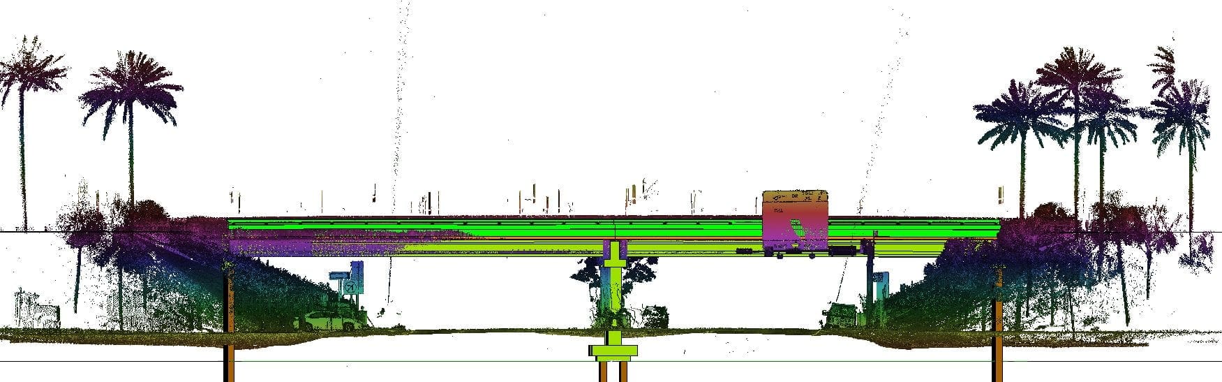
Previously, structural engineers relied on as-builts and 2D survey to help determine existing bridges’ geometry. Today, we have 3D survey in the form of Point Clouds and Digital Terrain Models (DTM). These forms of data collection, usually referred to as LiDAR (Light Detection and Ranging), along with the OpenBridge Modeler (OBM), provide us more precise measurements, allowing better design decisions. For bridge widenings, the process starts with recreating the existing bridge in an OpenBridge file using the as-built plans.
We then compare the point cloud to the as-built plan bridge models to finalize the existing bridge model for use with the final design. The DTM of the bridge deck surface is utilized to establish the existing top-of-deck elevations, the bridge’s cross slope, the coping limits, and the begin/end bridge limits. This refinement in a 3D environment improves the accuracy of the existing beam locations, top-of-deck elevations, substructure geometry, orientation of exposed pile foundations, as well as proposed drainage, existing drainage and utilities — all key elements in typical bridge-widening projects. Knowing and seeing the location of all aspects of a project, allows the design team to better identify constructability issues, like crane placements or other geometric conflicts.
OpenBridge is best when modeling and designing a brand-new bridge, but bridge widenings pose more challenges. For example, the existing bridge typically has different properties or dimensions than the proposed bridge widening (e.g., material properties or deck thicknesses). Multiple bridges and units can be added to the model to overcome this challenge; however, this could result in slow processing speeds and potentially lead to software crashes and a corrupt file. Currently, the best way to model a bridge widening is to create one file with the existing bridge modeled and a separate file with the proposed bridge widening. You can then reference both the existing and proposed bridges into a master file from which plan sheets are created. There’s an additional benefit to having the files separated when progressing from modeling into the design phase: existing conditions are unnecessary to complete the actual bridge design.
Coordination Between Roadway and Structures for 3D
Tutorials and presentations sometimes imply that 3D bridge model production can be completed with relative ease. In reality, the typical project requires a lot of coordination between multiple disciplines, especially between the roadway and structural engineers. The bridges designed in OpenBridge are built from the horizontal and vertical geometry set by roadway. When designing a bridge in OpenBridge, the first step is importing or referencing in the horizontal and vertical geometry. Note that if the geometry is imported live into the file and roadway geometry is modified, it will not update without reimporting the revised file. The preferred option is referencing the roadway alignment to facilitate direct updates.
The approach slabs and retaining/MSE walls are included in the roadway templates. It is necessary for roadway and structures to maintain communication while setting begin/end wall limits and leveling pad depths for MSE wall design. The 3D model helps to identify MSE retaining wall limits by clearly depicting the vertical profile. By clearly depicting the vertical profile, the roadway and structural engineers can use engineering judgment on the limits and feasibility of the different types of retaining walls (MSE, gravity, segmental block, barrier, etc.) This is an improvement on the rudimentary process of interpolating between the standard cross sections or requiring additional cross-sections. By including proposed and existing drainage features in the 3D model, potential conflicts with retaining walls, wall zone criteria, bridge foundations, and utilities can be easily identified.
Many things have changed over the years — except our clients’ expectations. As a profession, we must keep up with change, which means making the investment into 3D design, adapting and integrating as we go, and getting ahead of the next big hurdle.